How Does a Digital Thermometer Work? The Complete Science Explained

What Is a Digital Thermometer — and Why Does It Matter?
You reach for one almost without thinking: the slim device you press to a forehead during a fever, the probe buried in a roast chicken to check doneness, the gun-shaped sensor aimed at a solar panel on a blistering July afternoon. The digital thermometer has become one of the most quietly consequential instruments in modern life, trusted by hospitals, kitchens, laboratories, HVAC technicians, and parents checking on unwell toddlers at 2 a.m.
Yet most people have only the vaguest sense of what happens inside that plastic casing during the two or three seconds before a number appears on the screen. Is it magic? Close enough — but it is, in fact, a beautifully orchestrated sequence of physics, materials science, and signal processing that converts molecular vibration into legible digits.
This guide dismantles the mystery completely. We will walk through every layer of the process — from the atomic mechanics of temperature-sensitive materials, through electronic signal pathways, analog-to-digital conversion, and display logic — so you leave with a thorough, expert-level understanding of exactly how a digital thermometer works. Along the way, we will compare different sensor technologies, explore how infrared models pull off the seemingly impossible trick of reading temperature without contact, examine calibration science, and help you choose the right device for your needs.
Let’s go deeper — much deeper — than that.
Core Components Inside a Digital Thermometer
Before we trace the journey of a temperature reading from start to finish, it helps to know which parts are doing the work. A digital thermometer is, at its heart, a miniaturized measurement system. Each component has a precise role, and understanding those roles makes the whole process click into place.
Fig. 1 — Internal signal flow in a typical digital thermometer
Temperature Sensor Types
The sensor is the front door of the entire process. It is the component that physically interacts with the environment being measured and produces an electrical signal that represents temperature. Modern digital thermometers use one of four main sensor technologies:
Thermistor (NTC)
Most common in medical/consumer devices. Resistance drops dramatically as temperature rises. Inexpensive, highly sensitive.
Thermocouple
Two dissimilar metals create a voltage at their junction. Excellent for extreme temps (up to 2,300°C). Used in industrial & kitchen probes.
RTD / Pt100
Platinum wire with highly linear resistance change. Exceptional accuracy ±0.1°C. Preferred in laboratories and precision instruments.
Infrared (IR)
Detects thermal radiation (photons) emitted by objects. Enables non-contact measurement. Used in forehead thermometers & industrial scanners.
The Circuit Board: The Brain of the Operation
Behind every sensor lies a printed circuit board (PCB) that is, by consumer electronics standards, remarkably compact and refined. The PCB houses several critical subsystems:
- Voltage reference circuit: Supplies the stable, known voltage needed to accurately read sensor changes. Without it, battery fluctuations would cause false readings.
- Wheatstone bridge or current source: Applies a precise electrical excitation to the sensor so that resistance changes can be detected as voltage changes.
- Operational amplifier (op-amp): Amplifies the tiny sensor signal — sometimes just a few millivolts — to a level the ADC can interpret without introducing noise.
- Analog-to-Digital Converter (ADC): The translator that converts continuous electrical values into discrete binary numbers the microprocessor understands.
- Microcontroller Unit (MCU): A tiny computer that applies linearization algorithms, compensates for sensor non-linearities, and formats the output for display.
- LCD/LED driver circuit: Controls which segments of the display are illuminated to show the correct digit.
- Buzzer or alarm driver: Optional. Signals when a threshold temperature is reached or when measurement is complete.
In a basic oral thermometer, all of this circuitry fits on a PCB no larger than your thumbnail, which is a remarkable feat of miniaturization when you consider the precision required.

Trusted by chefs and parents alike. Waterproof, ±0.9°F accuracy, 2-second reading.
View on AmazonHow a Digital Thermometer Actually Measures Temperature
Here is where the physics becomes genuinely fascinating. Temperature, at the most fundamental level, is a measure of the average kinetic energy of molecules in a substance — how violently they are vibrating, bouncing, and colliding. But circuits cannot measure “vibration” directly. They can measure electrical properties like resistance, voltage, and current. The genius of temperature sensor design is in creating materials that create a predictable, reproducible bridge between molecular energy and electrical behavior.
Thermistor Mechanics: Resistance Is (Not) Futile
The word “thermistor” is a portmanteau of “thermally sensitive resistor,” which perfectly describes what it does. Thermistors are made from sintered metal oxide ceramics — typically mixtures of manganese, nickel, cobalt, copper, or iron oxides pressed into tiny beads or disks, then given metal leads and encapsulated in glass or epoxy.
The key physics: in a semiconductor material (which most thermistor ceramics are), electrons do not freely flow as they do in a metal. They sit in bound energy states and need thermal energy to “jump” into the conduction band where they can carry current. As temperature rises, more electrons gain enough energy to jump, so the material becomes more conductive — meaning its resistance decreases.
This gives us what engineers call the NTC (Negative Temperature Coefficient) behavior: resistance decreases as temperature increases. The relationship is not linear — it follows an exponential curve described by the Steinhart-Hart equation:
1/T = A + B·ln(R) + C·(ln(R))³where T is absolute temperature in Kelvin, R is resistance in ohms, and A, B, C are material-specific constants.
Fig. 2 — NTC thermistor: resistance drops exponentially as temperature rises
In practice, the circuit applies a known, stable current through the thermistor and measures the resulting voltage. Since voltage = current × resistance (Ohm’s Law), and the current is fixed, any change in voltage directly reflects a change in resistance, which the MCU translates to a temperature value using a pre-programmed lookup table or the Steinhart-Hart formula.
Thermocouple Mechanics: Two Metals, One Voltage
Thermocouples operate on a completely different physical principle: the Seebeck effect, discovered in 1821 by physicist Thomas Johann Seebeck. When two dissimilar metals are joined at one end (the “hot junction”) and the other ends are kept at a reference temperature (the “cold junction”), a small voltage is generated that is proportional to the temperature difference between the two junctions.
Fig. 3 — The Seebeck effect: dissimilar metals generate voltage proportional to temperature difference
The voltage generated is tiny — typically around 40–50 microvolts per degree Celsius for a common Type K thermocouple. The circuit must amplify this signal significantly before the ADC can read it reliably. Modern thermocouple amplifier ICs (like the MAX31855) do this on a single chip, also performing cold-junction compensation to account for the temperature at the reference end.
Different metal pairings produce different sensitivities and temperature ranges. The most common types are:
| Type | Metal Pairing | Temperature Range | Sensitivity | Common Use |
|---|---|---|---|---|
| Type K | Chromel / Alumel | -200°C to +1260°C | ~41 µV/°C | General purpose, most common |
| Type J | Iron / Constantan | -40°C to +750°C | ~51 µV/°C | Plastics, older equipment |
| Type T | Copper / Constantan | -200°C to +350°C | ~43 µV/°C | Cryogenic, food processing |
| Type S | Platinum-Rhodium / Platinum | 0°C to +1480°C | ~10 µV/°C | Furnaces, foundries |
| Type N | Nicrosil / Nisil | -270°C to +1300°C | ~39 µV/°C | High-temp industrial |
RTD and Platinum Sensors: The Accuracy Champions
Resistance Temperature Detectors (RTDs) occupy the premium end of the temperature sensing spectrum. Unlike thermistors — which are semiconductors — RTDs are made from pure metals, most commonly platinum. The most widespread standard is the Pt100 (100 ohms at 0°C) and Pt1000 (1000 ohms at 0°C).
In a metal, the mechanism is opposite to a semiconductor: as temperature rises, increased atomic vibration scatters the freely moving electrons, increasing resistance. This gives RTDs a PTC (Positive Temperature Coefficient) — resistance increases with temperature. The relationship is extremely linear over a wide range, governed by the Callendar-Van Dusen equation, but roughly:
R(T) = R₀ × [1 + α(T − T₀)]For Pt100: α ≈ 0.00385 Ω/Ω/°C. So at 100°C, R ≈ 138.5 Ω.
Fig. 4 — RTD (platinum) offers superior linearity vs thermistor exponential curve
The extraordinary linearity of RTDs means less computational work for linearization — what you measure is very close to what the temperature actually is. Coupled with platinum’s chemical stability and excellent reproducibility, RTDs achieve accuracies of ±0.1°C or better, making them the gold standard for laboratory and pharmaceutical applications. The tradeoff is cost: platinum is expensive, and RTD circuits are more complex than thermistor circuits.

NTC thermistor sensor, ±1°F accuracy, 3-second reading. Perfect for cooking and BBQ.
Check Price on AmazonSignal Processing and the Analog-to-Digital Converter
Having a sensor that changes its electrical properties with temperature is only half the story. The next challenge is extracting a useful measurement from those changes — and that is where signal conditioning and analog-to-digital conversion come in.
Imagine the thermistor in a medical thermometer. At 37°C (98.6°F), it might have a resistance of around 4,700 ohms. At 38°C (fever territory), it might be 4,580 ohms. That is a change of just 120 ohms — a difference of roughly 2.5%. The voltage across the thermistor in a simple voltage divider circuit might shift by only 20–30 millivolts. The ADC needs to distinguish between temperatures 0.1°C apart. That means it must reliably detect voltage differences as small as 2–3 millivolts. At 3.3V supply voltage, that is a 0.1% change.
Fig. 5 — Four-stage signal chain: sensor → amplifier → ADC → microcontroller
To achieve this, engineers deploy several techniques:
- High-resolution ADCs: Modern thermometers use 12-bit to 24-bit ADCs. A 16-bit ADC can distinguish between 65,536 discrete voltage levels, making sub-0.01°C resolution achievable in theory.
- Oversampling and averaging: The MCU may take 64 or 128 ADC readings and average them, which mathematically improves effective resolution by the square root of the number of samples.
- Anti-aliasing filters: Low-pass filters on the analog side prevent high-frequency electrical noise (from power supplies, radio frequency interference, or nearby motors) from corrupting the reading.
- Ratiometric measurements: Using the same reference voltage for both the sensor excitation and the ADC reference cancels out power supply variations.
- Linearization lookup tables: The MCU stores a calibration curve in non-volatile memory (EEPROM or Flash). Every ADC code maps to a specific temperature, accounting for the sensor’s non-linear response.
The analog-to-digital converter is the moment where the physical world becomes a number — and the quality of everything before it determines the quality of that number.
— Principles of Electronic Instrumentation
The resolution of the final display is, somewhat counterintuitively, often less than the internal processing resolution. A thermometer might process at 16-bit resolution internally (1/65536 of full scale) but display only to 0.1°C. This headroom is intentional — it gives the firmware room to perform smoothing, reject noise spikes, and still deliver a stable, trustworthy reading to the user.
The Display System: Turning Numbers Into Readable Output
Once the microcontroller has calculated the temperature value, it needs to present that information to the user. This is done through a display driver — a small circuit that translates binary numbers into the correct pattern of illuminated segments or pixels.
Fig. 6 — 7-segment LCD display: segments a–g illuminate in combinations to form any digit
Most digital thermometers use one of two display technologies:
LCD (Liquid Crystal Display): The dominant choice for battery-powered devices. LCDs do not emit light — they modulate ambient or backlight illumination by aligning liquid crystal molecules using electric fields. The key segments are controlled by sending alternating AC voltage signals (direct DC would destroy the liquid crystals over time). LCDs consume extremely little power — sometimes as low as a few microamps — which explains why a AAA battery in a medical thermometer can last years.
LED (Light-Emitting Diode) displays: Used in kitchen thermometers and oven thermometers where visibility in bright environments or from a distance matters. LEDs are far brighter but also far more power-hungry — a single 7-segment LED display can draw 30–80mA, versus the 0.01–0.1mA of an LCD. Most LED thermometer displays therefore require larger batteries or a power adapter.
The MCU controls the display using a concept called multiplexing. Rather than wiring a separate output to every segment of every digit (which would require dozens of MCU pins), the display digits are scanned rapidly in sequence. The MCU illuminates digit 1’s segments for 1 millisecond, then digit 2’s, then digit 3’s, cycling at 100–500Hz. Because this cycle is far faster than the human eye’s refresh rate (~24Hz), the display appears fully lit and stable. This multiplexing trick reduces pin requirements dramatically and is why most 4-digit thermometer displays only need 7 segment pins + 4 digit-select pins, rather than 28.
A Complete Comparison of Digital Thermometer Types
Not all digital thermometers work the same way under the hood. The choice of sensor, measurement method, and form factor produces very different instruments suited to very different tasks. If you are considering purchasing one of the best digital thermometers available today, understanding these differences will help you make a much more informed choice.
| Type | Sensor | Accuracy | Response | Contact? | Best For | Price Range |
|---|---|---|---|---|---|---|
| Oral / Axillary | NTC Thermistor | ±0.1°C | 10–60s | Yes | Medical, body temp | $8–$30 |
| Ear (Tympanic) | IR Sensor | ±0.2°C | 1–2s | Partial | Infants, quick checks | $25–$80 |
| Forehead (Temporal) | IR Sensor | ±0.3°C | 1s | No | Contactless screening | $30–$100 |
| Instant-Read Meat | Thermocouple | ±0.5°C | 2–4s | Yes | Cooking, BBQ | $15–$60 |
| Oven/BBQ Leave-In | NTC / Thermocouple | ±1–2°C | Continuous | Yes | Long-cook monitoring | $20–$80 |
| Industrial IR Gun | Thermopile IR | ±1–2°C | 0.5s | No | HVAC, electrical panels | $20–$300 |
| Lab / RTD | Pt100 RTD | ±0.01°C | 5–30s | Yes | Scientific, pharmaceutical | $100–$2000 |
| Wireless / Smart | NTC / Thermocouple | ±0.5–1°C | 2–5s | Varies | Remote monitoring, IoT | $40–$200 |
✅ Advantages of Digital Thermometers
- Easy-to-read digital display
- Much faster than mercury types
- Safe — no toxic materials
- Alarm and memory functions
- Celsius/Fahrenheit switching
- Battery-powered, portable
- Can store multiple readings
- Wireless connectivity options
❌ Limitations to Know
- Requires battery (can die)
- Needs periodic recalibration
- IR models affected by surface emissivity
- Cheap models can drift over time
- Less accurate than lab instruments
- Probe models require proper placement

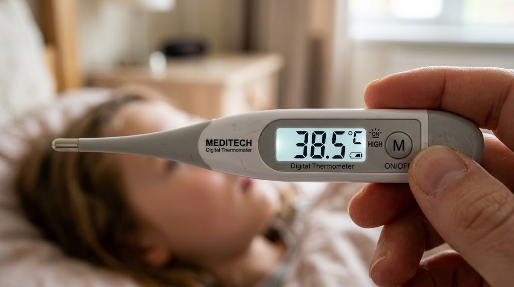
1-second reading, fever alarm, dual mode (body + object). FDA-cleared for medical use.
View on AmazonHow Infrared (Non-Contact) Digital Thermometers Work
Infrared thermometers represent one of the most elegant applications of quantum physics in everyday instrumentation. They achieve something that seems almost impossible: measuring an object’s temperature without touching it, often from several inches or even feet away, in under a second. Understanding how they do this requires a short excursion into the physics of thermal radiation.
Every object above absolute zero (0 Kelvin, −273.15°C) emits electromagnetic radiation. The spectrum and intensity of this radiation is determined entirely by the object’s temperature and surface properties. This is described by Planck’s Law and the Stefan-Boltzmann Law. For objects at typical earthly temperatures (say, 0°C to 200°C), most of the emitted radiation falls in the mid-infrared range — wavelengths of roughly 8–14 micrometers, far beyond visible light.
Fig. 7 — IR thermometer optical path: thermal radiation → Fresnel lens → thermopile → signal processing → temperature display
The Thermopile Detector
The heart of an IR thermometer is a component called a thermopile — essentially a series of thermocouples connected in a chain, with alternate hot junctions exposed to the incoming infrared radiation and cold junctions thermally anchored to a stable reference (usually the thermometer body). As infrared photons strike the exposed junctions, they heat them slightly; the temperature difference between hot and cold junctions generates a tiny voltage via the Seebeck effect.
The voltage from a typical thermopile might be only 10–100 microvolts for a small temperature difference, so the signal must be heavily amplified. A precision op-amp boosts the signal, which is then fed to the ADC and MCU for processing.
The Emissivity Problem
Here is where infrared thermometry gets nuanced. The Stefan-Boltzmann law assumes a perfect blackbody — an object that absorbs and emits all radiation at 100% efficiency (emissivity ε = 1.0). Real materials have emissivity values between 0 and 1. Human skin has ε ≈ 0.98 — almost perfect — which is why IR forehead thermometers are quite accurate. But a polished aluminum surface has ε ≈ 0.05, which means it emits only 5% of what a blackbody would. An uncorrected IR thermometer pointed at polished aluminum would massively underestimate its temperature.
Professional IR thermometers have adjustable emissivity settings. Consumer medical IR thermometers get around this by being factory-calibrated to human skin emissivity and should not be used to measure object temperatures.

Adjustable emissivity, D:S ratio 12:1, range −58°F to 1022°F. Perfect for HVAC & electrical work.
Check Price on AmazonCalibration, Accuracy, and What Affects Your Reading
Knowing how to read a thermometer and knowing whether that reading is trustworthy are two different things. Calibration is the process of comparing a thermometer’s output to a known standard and either confirming it is accurate or adjusting it until it is. Every measurement instrument, no matter how precise, drifts over time as components age, as the sensor accumulates deposits, or as the reference circuit’s components drift.
What Calibration Actually Involves
At the factory, a thermometer is calibrated by placing it in a controlled environment at several known temperatures — typically using a dry block calibrator (a precisely temperature-controlled metal block with a probe well) or a liquid bath calibrator (a stirred fluid at a precise temperature). The thermometer’s raw output is compared to the reference standard (usually a NIST-traceable platinum RTD), and any offset or gain error is corrected in the firmware’s calibration table.
| Error Source | Cause | Typical Magnitude | Mitigation |
|---|---|---|---|
| Offset error | Constant shift at all temps | ±0.1–0.5°C | Factory single-point calibration |
| Gain error | Error increases with temp | ±0.05–0.2% of reading | Two-point calibration |
| Non-linearity | Sensor curve not perfectly modeled | ±0.05–0.3°C | Multi-point calibration + lookup table |
| Self-heating | Sensor current heats the sensor | ±0.01–0.1°C | Low-excitation current, pulsed measurement |
| Thermal lag | Sensor equilibration time | 0–2°C initially | Wait for stable reading / adequate probe immersion |
| Emissivity error (IR) | Incorrect emissivity setting | ±1–15°C | Adjust emissivity setting for target surface |
| Ambient drift | Electronics temperature changes | ±0.05–0.2°C/°C | Temperature compensation in firmware |
Why Calibration Drifts Over Time
Semiconductor materials slowly change their doping profiles. Metal oxide thermistors can absorb moisture, changing their resistance characteristics. Thermocouple wires experience grain boundary migration at high temperatures. Even platinum RTDs are not immune — wire contamination and mechanical stress introduce small errors. For critical medical or laboratory applications, recalibration every 1–2 years is standard practice. For consumer use, most quality thermometers remain within their stated accuracy for 5+ years under normal use.
Digital Thermometers vs. Analog Thermometers: A Direct Comparison
Before the digital revolution swept through measurement technology, the analog glass thermometer — the slender tube of mercury or colored alcohol — was the universal standard. Understanding what changed and why digital won will deepen your appreciation of what makes the modern device tick.
| Feature | Digital Thermometer | Analog (Glass) Thermometer |
|---|---|---|
| Reading method | Automatic display | Manual visual reading |
| Accuracy | ±0.1–0.5°C (consumer) | ±0.5–1.0°C (reading error) |
| Response time | 2–60 seconds | 1–3 minutes (oral) |
| Safety | Safe (no toxic materials) | Mercury is toxic if broken |
| Readability | Clear digital display | Requires good eyesight, lighting |
| Power needed | Battery required | None |
| Features | Memory, alarms, wireless | None |
| Durability | Electronic components can fail | Can break if dropped |
| Lifetime cost | Battery replacements | Zero ongoing cost |
| Range | Programmable, wide range possible | Fixed by fluid type |
| Regulatory status | Approved for medical use | Mercury banned in many countries |
The digital thermometer’s dominance is not simply a matter of fashion or technological novelty. The combination of speed, safety, ease of reading, and added features genuinely makes it a superior instrument for nearly every application. The only scenarios where analog retains an edge are situations without a power source and certain specialty laboratory applications where a carefully maintained liquid-in-glass thermometer remains the calibration reference standard.
Real-World Applications of Digital Thermometers
The versatility of digital thermometer technology is staggering. By choosing the appropriate sensor type, packaging, and calibration range, the same fundamental circuit architecture powers instruments used across radically different fields.
Medical and Clinical Settings
In hospitals and clinics, digital thermometers must meet strict regulatory standards — in the USA, the FDA Class II medical device requirements, and in Europe, the CE marking under the Medical Devices Directive. Clinical oral/axillary thermometers typically specify accuracy of ±0.1°C, with ASTM E1112 and IEC 60601 standards governing their performance testing. Tympanic (ear) thermometers that measure the eardrum’s temperature — which closely correlates with core body temperature — use highly sensitive thermopile detectors with sophisticated signal processing to compensate for ear canal geometry and variation.
Food Service and Kitchen Applications
In commercial kitchens and home cooking, digital thermometers serve as both safety instruments and culinary tools. The USDA specifies minimum internal cooking temperatures — 165°F (74°C) for poultry, 145°F (63°C) for whole cuts of beef, pork, and fish. A high-quality instant-read kitchen thermometer with a thermocouple sensor can confirm these temperatures in 2–3 seconds, making it an indispensable food safety device. Wireless probe thermometers allow competitive BBQ cooks and sous-vide chefs to monitor internal temperature continuously over hours of cooking without opening the oven or smoker.
Industrial and Engineering Applications
Industrial IR thermometers are workhorses in manufacturing, HVAC, and electrical maintenance. An HVAC technician uses an IR gun to check temperature differentials across ductwork and to identify refrigerant leaks by the temperature anomalies they create. An electrician sweeps an electrical panel with an IR thermometer to find overheating connections — hotspots that would be invisible to any other non-invasive instrument. In semiconductor fabrication, platinum RTD arrays monitor wafer temperatures in deposition chambers to nanometer precision, since even small temperature non-uniformities translate into yield losses.
Environmental Monitoring
Weather stations, greenhouses, server rooms, cold-chain logistics, pharmaceutical storage, and museum climate control all rely on digital temperature sensors — often the same NTC thermistor or RTD technology in a weatherproof enclosure, connected to dataloggers, IoT gateways, or building management systems. Smart refrigerators use NTC thermistors to regulate their compressors. Automotive ECUs (Engine Control Units) use NTC thermistors to read coolant temperature, intake air temperature, and transmission fluid temperature — feeding these values into fuel injection calculations dozens of times per second.

Bluetooth & WiFi connectivity, data export, 2-year data history, smart alerts. Perfect for smart homes & greenhouses.
Shop on AmazonHow to Choose the Right Digital Thermometer for Your Needs
Armed with a thorough understanding of how digital thermometers work, choosing the right one becomes a matter of matching sensor technology and design to your specific application. Here is a framework for making that decision well.
1 Define your application first. Medical body temperature measurement, food cooking, industrial surface scanning, and environmental monitoring each have different accuracy requirements, temperature ranges, and response time needs. Never buy on price alone without considering the application.
2 Check the accuracy specification — and understand what it means. A ±1°C accuracy specification means the display could be 1 degree higher or lower than the true temperature. For a fever check, this might be acceptable; for sous-vide cooking at 57°C (the precise edge of food safety for pasteurization), it is not. Always read the full specification, including the temperature range over which accuracy is guaranteed.
3 Consider response time vs. convenience. Thermocouple probes respond in 2–4 seconds; NTC thermistors in a medical device may take 10–60 seconds. IR sensors respond almost instantaneously. Faster is not always better — a fast sensor that gives an unstable reading may be less useful than a slower one that gives a settled, reliable value.
4 Evaluate the display and usability. Will you be reading the thermometer in a dimly lit room? A backlit display is worth paying for. Will you be wearing gloves? Large buttons and auto-hold functions matter. Will the probe be inserted into liquids? Look for an IP67 or IP68 waterproof rating.
5 Look for certifications relevant to your use case. Medical thermometers should be FDA 510(k) cleared (USA) or CE marked (EU). Food service thermometers should comply with NSF standards for sanitation. Industrial IR thermometers should specify D:S ratio (distance-to-spot ratio) — a 12:1 ratio means the measurement spot diameter is 1/12 of the distance. At 24 inches, the spot is 2 inches across.
6 Consider long-term cost and support. Budget thermometers often lack the sensor quality and firmware refinement to maintain accuracy over years of use. A mid-range thermometer from a reputable manufacturer — with documented calibration traceability, replaceable probes, and a warranty — will typically serve better over the long term. For medical applications, consider devices that support recalibration or have a documented calibration interval.
| Application | Recommended Type | Key Specs to Check | Budget Range |
|---|---|---|---|
| Baby / child fever | Forehead IR or oral digital | ±0.2°C, FDA cleared, beep alert | $30–$60 |
| Home cooking | Instant-read thermocouple | ±0.5°C, 2–3s, waterproof IP67 | $15–$35 |
| BBQ / smoking | Wireless probe with app | Dual probe, 300ft range, 0–300°C | $40–$100 |
| Homebrewing / candy | Probe thermometer with clip | 0–200°C, ±1°C, stainless probe | $20–$50 |
| HVAC maintenance | IR gun, high D:S ratio | 12:1 D:S, −50°C to 550°C, adj. emissivity | $40–$120 |
| Scientific lab | RTD reference thermometer | ±0.05°C, NIST traceable calibration | $200–$800 |
| Smart home / IoT | WiFi/Bluetooth sensor | ±0.3°C, app, data logging, alerts | $20–$80 |
For a curated selection of top-performing options across every category, the comprehensive guide to the best digital thermometers is an excellent starting point, with side-by-side performance comparisons and real-world testing notes.

165ft Bluetooth range, guided cook system app, simultaneous internal & ambient sensors. Zero wires.
View on AmazonFrequently Asked Questions About Digital Thermometers
How accurate is a digital thermometer compared to a mercury one?
High-quality digital thermometers are generally as accurate or more accurate than traditional mercury thermometers. Clinical digital thermometers typically specify ±0.1°C accuracy, which matches the ±0.1°C repeatability of a carefully read glass mercury thermometer — without the parallax reading error or the 3-minute wait time. The key advantage of digital instruments is eliminating the human reading error that glass thermometers are subject to. Lab-grade digital RTD thermometers surpass mercury precision entirely, achieving ±0.01°C or better.
Why does my digital thermometer give different readings each time?
Small reading-to-reading variation (within the stated accuracy spec) is normal and expected — it reflects the inherent measurement noise of any real sensor and circuit. Larger inconsistencies usually stem from measurement technique: placement variation (the probe is not in the same position each time), thermal equilibration time (the probe has not fully reached the target temperature), or environmental factors like a drafty room affecting an oral reading. If readings vary by more than 0.5°C consistently, the thermometer may need recalibration or replacement. Also confirm the battery is not low — a weak battery causes unstable reference voltage and erratic readings.
What does the response time of a digital thermometer mean?
Response time (also called time constant or T90) is the time it takes a thermometer to reach 90% of the true temperature value after a step change in temperature. It is determined primarily by the thermal mass of the sensor and the thermal resistance of its housing. A thin, bare thermocouple wire responds in milliseconds. A clinical thermometer’s probe, encased in plastic, responds in 10–60 seconds depending on design. Manufacturers often advertise a “1-second reading” for instant-read thermometers — this typically means 90% accuracy in 1 second, with full accuracy (to within spec) in 2–4 seconds.
Can a digital thermometer be used for both Celsius and Fahrenheit?
Yes, virtually all modern digital thermometers support both Celsius and Fahrenheit display. The conversion is performed internally by the microcontroller using the formula F = (C × 9/5) + 32. The sensor itself measures in a unitless electrical quantity (resistance or voltage) — the MCU translates this to a temperature number in whichever unit is selected. Most thermometers switch between units by holding a button for 2–3 seconds. The selection is stored in the MCU’s non-volatile memory, so it persists after the device is turned off.
How do ear (tympanic) thermometers work differently from forehead thermometers?
Both use infrared sensors, but the geometry and calibration differ significantly. Tympanic thermometers insert into the ear canal to get a direct view of the tympanic membrane (eardrum), which shares its blood supply with the hypothalamus — the brain’s temperature regulation center — making it an excellent proxy for core body temperature. The sensor is a precision thermopile with a waveguide lens tuned to the geometry of a typical ear canal. Forehead thermometers scan across the temporal artery on the forehead, integrating the heat emission over a sweep. Both require careful technique (correct ear canal angle for tympanic, proper sweep distance and speed for temporal) to give accurate results.
Does a digital thermometer need calibration, and how often?
All measurement instruments drift over time, and digital thermometers are no exception. For medical devices used clinically, calibration every 12 months is typically recommended. For food-service thermometers, calibration verification before each use (or at minimum weekly) is good practice — a simple ice-water check takes 30 seconds. For consumer medical thermometers, most maintain accuracy within specification for 2–5 years under normal use. If a thermometer is dropped, exposed to extreme temperatures, or gives readings that seem inconsistent with clinical symptoms, verification and likely recalibration is warranted.
Why is a non-contact infrared thermometer less accurate than a contact probe?
Several factors contribute. First, IR thermometers measure surface temperature, not internal (core) temperature — and surfaces can be cooler than interiors (a cooler room cools the skin, giving a falsely low forehead reading). Second, emissivity variation means the thermometer must make an assumption about how much radiation the surface emits — an assumption that may be imperfect. Third, the field of view of the thermopile averages radiation from an area, not a point — if that area includes both the target and cooler background, the reading is diluted. Fourth, ambient IR sources (sunlight, warm walls) can enter the optical path and bias the reading. Contact sensors avoid all of these issues by physically equilibrating with the target.
What is the difference between a thermistor and a thermocouple?
Thermistors are semiconductor ceramic devices whose electrical resistance changes dramatically with temperature — they are highly sensitive, inexpensive, and well-suited for the narrow temperature ranges of medical and consumer applications (typically −50°C to 150°C). Thermocouples operate on the Seebeck effect, generating a tiny voltage at the junction of two dissimilar metals — they are less sensitive per degree but excel over extreme temperature ranges (up to 2,300°C for specialized types). Thermocouples are the default choice for kitchen probes, industrial furnaces, and any application involving temperatures above 150°C. Thermistors dominate in medical, HVAC sensing, and battery management applications where high sensitivity in a narrow, moderate temperature range is paramount.
Can I calibrate my digital thermometer at home?
You can verify accuracy at home using two reference points: ice water (0°C / 32°F) and boiling water (100°C / 212°F at sea level, adjusted for altitude). If your thermometer reads within ±0.5°C of these reference points, it is likely within factory spec. Most consumer thermometers do not have user-accessible calibration adjustments — if the device is out of spec, it typically needs manufacturer service or replacement. Some professional kitchen thermometers do have a calibration button or offset adjustment accessible in the menu, allowing the user to trim the reading to match the reference. Always use an ice slurry (equal parts ice and cold water, well-stirred) rather than just cold water for the 0°C check.
What is an NTC thermistor and why is it used in most medical thermometers?
NTC stands for Negative Temperature Coefficient — meaning the thermistor’s resistance decreases as temperature increases. NTC thermistors are manufactured from metal oxide semiconductors (manganese, nickel, cobalt oxides) and are chosen for medical thermometers for several compelling reasons: they offer very high sensitivity (a large resistance change per degree, making them easy for circuits to detect), they are inexpensive to manufacture in consistent batches, they are physically tiny (allowing a slim probe tip), and they operate with very low power consumption (critical for battery life). Their main limitation — a non-linear resistance curve — is handled by the MCU’s linearization algorithm, which is programmed at the factory using sensor characterization data.
The Invisible Engineering Behind Every Reading
From the semiconductor physics of a metal oxide bead to the electron flow in a thermocouple junction, from the quantum mechanics of blackbody radiation to the binary arithmetic of a microcontroller lookup table — the humble digital thermometer is a miracle of applied science crammed into a device that costs less than a restaurant meal.
Understanding how it works makes you a smarter user, a more informed buyer, and someone who can troubleshoot when readings seem off. Whether you are a parent checking a sick child’s temperature, a chef chasing the perfect sear, or an engineer diagnosing an overheating circuit board, the same fundamental chain of physics, electronics, and clever software is working on your behalf every time you press that button.
Ready to find the right device for your needs? Explore the full range of options across every use case, budget, and sensor type in our comprehensive buyer’s guide.
Browse the Best Digital Thermometers →
3-in-1: forehead, ear, and object mode. Color-coded fever guidance, 60-reading memory. Clinically validated.
View on Amazon